Fan Coil Diagnostics: Why Real-Time Verification Protects Variable-Speed Performance
HVAC OEMs specify variable-speed fan coil systems with EC motors and proportional control valves to reduce auxiliary energy compared with fixed-speed equipment. That outcome only appears if the system actually modulates after installation.
When it does not, the efficiency case that justified the design never shows up in the field. Energy use looks closer to the equipment that was replaced, and the OEM is left explaining the gap.
The problem is not the motor
It’s not unusual for a unit to pass a capacity test at design load, receive a commissioning sign-off, and still consume energy like a fixed-speed system months later. In many of those cases, the motor hasn’t failed, and the valves aren’t seized.
The control sequence, thermostat, actuator wiring, or temperature sensing wasn’t verified under part-load conditions, where fan coils spend most of their operating hours. Without real-time fan coil diagnostics, that gap is easy to miss. A walk-through at 100% heating load will look correct even if the fan speed command remains at maximum, a valve doesn’t follow its control signal, or a sensor has drifted. The system can continue operating at maximum without triggering a hard fault or alarm.
For OEMs, this typically shows up as energy complaints, warranty activity, and the conclusion that the EC motor didn’t deliver the expected savings. In many cases, the issue isn’t the hardware itself, but the controls and commissioning process.
Nameplate ratings reflect laboratory performance. Delivered performance depends on whether fan speed and valve position actually respond to demand in the field. The practical response is to design diagnostic visibility into the controller. This enables technicians to verify and troubleshoot modulation during commissioning and after occupancy.
What has to stay in sync
Variable-speed operation depends on more than the EC motor. Fan speed, water flow, and demand have to stay aligned. If any of the following is out of sync, the unit can sit at full output even when the hardware is intact:
- EC motor speed command (PWM or 0–10V) and actual fan speed
- Proportional valve actuation (0–10V or equivalent)
- Room and coil temperature sensing
- Thermostat logic, including setpoint and deadband
- BMS communication and setpoint override, where applicable
A fault in any of these can degrade the system without appearing to be an equipment failure. Avnan’s Fan Coil Control & Diagnostic Platform is built to control and expose those points: PWM or 0–10V EC motor control, on/off or modulating actuators, multi-sensor inputs, BACnet, and a BLE app that provides real-time temperature, fan speed, valve position, system status, and operating mode.
Confirm fan speed at part-load, not only at nameplate
EC motors reduce auxiliary power when their speed is allowed to follow the load. If the speed command remains at maximum under reduced demand, the motor can operate much like the fixed-speed unit it replaced.
Full-load commissioning may not catch that condition. A reduced-demand test (lowering the setpoint or otherwise simulating part-load) is required to confirm that fan speed responds appropriately to demand. If speed stays at maximum, the fault is typically upstream of the motor: thermostat logic, control configuration, or command wiring.
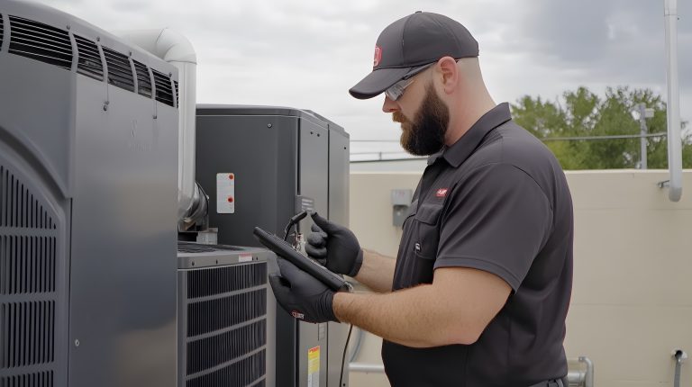
For OEMs, this type of verification can only be performed effectively in the field when the controller provides the necessary visibility. Avnan’s BLE diagnostic app is designed for this purpose, giving technicians real-time visibility into fan speed and operating mode without the need to disassemble the unit.
Compare valve position to the control signal
Modulating valves are a frequent source of commissioning issues. Common problems include an unpowered actuator that is stuck open or closed, reversed control-signal polarity, an incorrect actuator stroke or calibration range, and an isolation valve that is left partially closed, limiting flow regardless of the proportional command.
Verification is straightforward: Change the system demand and confirm that the valve position responds in the correct direction and in proportion to the control signal. If the command changes and the valve position doesn’t , the sequence isn’t responding as intended, regardless of what the thermostat display indicates.
Valve position is one of the real-time parameters available through Avnan’s BLE diagnostic app, along with system status and operating mode. A technician can use this information to confirm that the valve is actually responding when system demand changes, helping identify control or commissioning issues without having to disassemble the unit.
Validate temperature sensors before they run the loop
Room and coil sensors help determine system demand and control response. A drifted thermistor or RTD doesn’t present as a failed component. The fan may appear to modulate while the loop is responding to an inaccurate temperature reading, underheating in one direction or overheating or running at full output in the other.
During commissioning, controller readings should be compared with a reference instrument at the same points: the room sensor versus a handheld probe, and the coil leaving-air or water temperature versus a calibrated thermometer. A significant difference points to a calibration or placement issue that should be corrected before handover. Avnan’s diagnostics article lists sensor drift, signal loss, and calibration issues among the parameters that edge-enabled controllers can monitor and provide alerts for. Displaying those readings alongside fan speed and valve position gives technicians a clearer picture of cause and effect during a single service visit.
Keep diagnostic access after handover
Commissioning is a snapshot. Sensors drift, BMS overrides are added, and control sequences are edited. If verification happens only on the day of startup, issues such as silent full-speed operation can return over time.
Embedded diagnostics such as fault detection, live operating data, and a technician app give OEMs a way to support and troubleshoot the product after it leaves the factory. That’s the difference between offering variable-speed as a feature and delivering the intended variable-speed performance in the field.
Key Takeaways
- Variable-speed fan coils deliver energy efficiency only if they modulate in the field. A full-load test alone doesn’t prove part-load control.
- Fan coil diagnostics should include live fan speed, valve position, and temperature readings, rather than relying solely on and not a pass/fail check at nameplate conditions.
- Control-signal errors, actuator setup, and sensor drift are common sources of silent faults. None of them require a failed motor.
- OEMs build this diagnostic visibility into the controller and technician app so commissioning and service can verify operation after handover.
- Nameplate ratings are laboratory performance. Delivered performance depends on effective controls, commissioning, and ongoing verification in the field.
Looking For A Partner?
If you’re looking for a partner to help you build your electronic controls solution, contact us.
Related Posts
Optimizing Fan Coil Auxiliary Energy in Heat Pump Systems
Heat pump hydronic systems are increasingly designed to operate at lower supply water temperatures (typically 30–45°C instead of legacy 55–65°C) to improve efficiency and meet evolving efficiency requirements. However, the circulation pump and fan motors…
5 Costly Mistakes That Delay HVAC Product Development
Every HVAC OEM engineering team has lived through it: a launch date that looked comfortable six months ago is suddenly at risk, and pointing to a single root cause can get challenging. With decisions made too…
How HVAC OEMs Can Scale Engineering Without Hiring More Engineers
Is this scenario too familiar? Your HVAC product roadmap is packed with next-generation designs – from smart thermostats to advanced heat pump controls – yet your engineering team is already working at full tilt. New…